Hardware Description
Physical Specification
Dimension |
174×134×56mm |
Temperature |
Operating: -40°~85° |
Weight |
950g |
Storage: -55°~95° |
|
Protection Class |
IP67 |
Vibration |
GKB150.18-2009, MIL-STD-810 |
Humidity |
95% non-condensing |
Shock |
GKB150.18-2009, MIL-STD-810 |
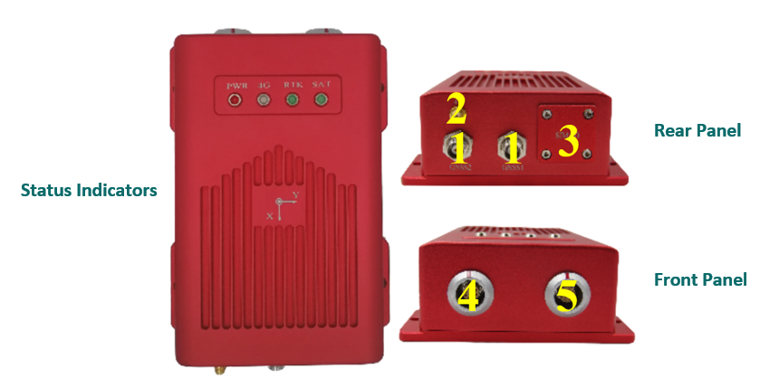
Interface
Interface |
Description |
Pin function |
|
Front Panel |
|||
4 |
10-pin MGG connector |
USB, CAN, COM3 |
Refer to the table below |
5 |
12-pin MGG connector |
Ethernet port, PPS, COM2, power interface |
Refer to the table below |
Rear Panel |
|||
1 |
NC connectors |
GNSS Dual Antenna |
|
2 |
SMA connector |
4G Antenna |
|
3 |
Card slots |
SD Card, SIM Card |
|
Status Indicators |
|||
PWR |
Power Indicator |
Refer to the table below |
|
4G |
4G signal light |
Refer to the table below |
|
RTK |
RTK indicator |
Refer to the table below |
|
SAT |
Satellite indicator |
Refer to the table below |
|

10-pin MGG connector pin function
Number |
Name |
Function |
1 |
CAN_L/422_TX- |
Bus low/422 send negative |
2 |
CAN_H/422_TX+ |
Bus high/422 sending positive |
3 |
GND |
Ground |
4 |
USB_VBUS |
Bus powered |
5 |
USB_ID |
Determine the master and slave device |
6 |
GND |
Ground |
7 |
USB_D+ |
Data positive |
8 |
USB_D- |
Data negative |
9 |
TXD3/422_RX- |
Send data/422 receive negative |
10 |
RXD3/422_RX+ |
Receive data/422 receive positive |
12-pin MGG connector pin function
Number |
Name |
Funtion |
1 |
GND |
Ground |
2 |
N/A |
Keep |
3 |
GND |
Ground |
4 |
ETH_TX+ |
Ethernet send positive |
5 |
ETH_TX- |
Ethernet send negative |
6 |
GND |
Ground |
7 |
ETH_RX- |
Ethernet receive negative |
8 |
ETH_RX+ |
Ethernet receiving positive |
9 |
PPS |
Second pulse |
10 |
12V+ |
12V power input (input voltage 9-36VDC) |
11 |
RXD2 |
COM2 receive data |
12 |
TXD2 |
COM2 send data |
Antenna and Communication
Interface |
State |
Description |
ANT1 |
Master antenna |
Master antenna when built-in dual antenna board. |
ANT2 |
From the antenna |
When the dual antenna board is built-in, it is the slave antenna. |
4G |
4G signal antenna |
4G signal antenna. |
SIM |
SIM card slot |
SIM now supports North American and Mainland versions. If you need support from other countries, please contact the Aceinna support team for customized production. |
Indicator Satus
Indicator |
Status |
Description |

|
Satellite indicator |
Display the receiver accepts satellites:
1 No light: no satellite received
2 Flashing: fewer satellites have been tracked (<12)
3 Steady on: The number of tracked satellites is sufficient (>=12)
|

|
RTK indicator |
Display receiver positioning:
1 Breath (On 3s off 1s) The board is started, no RTCM data access
2 High frequency (25Hz) RTCM data access but no fixed solution or floating point solution
3 times high frequency (5Hz) to obtain floating point solution
4 Low frequency (1Hz) to obtain a fixed solution
|

|
4G signal light |
Show receiver 4G signal condition:
1 Flashing slowly (200ms High / 1800ms Low) Network search
2 Slow flashing (1800ms High / 200ms Low) invalid
3 Fast flashing (125ms High / 125ms Low) Data is being transmitted
4 Always on Busy
|

|
Power Indicator |
Always on, power on
|